

| Standard residential scale | 1/4" = 1 foot (1:48) (Common US architectural drafting convention) |
| Floor plan cut height | Approximately 4 feet above finished floor (Standard architectural drawing practice) |
| Dashed line meaning | Element located above the cut plane (Standard drafting notation) |
| Dimension string reference point | Face of framing, not finished surface (Standard US residential construction practice) |
| Typical drywall allowance per side | ~1 inch (Based on standard 5/8" drywall installation) |
What a Floor Plan Actually Shows
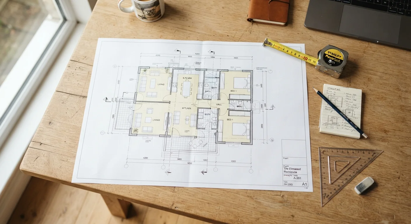
A floor plan is a scaled, bird's-eye cross-section of a building drawn as if the roof and upper walls have been removed. The standard cutting height is about four feet above the finished floor — high enough to capture windows, countertops, and most doorways in a single view.
Floor plans convey three categories of information: the structure (walls, columns, staircases), the openings (doors and windows), and the fixed elements (built-in cabinetry, plumbing fixtures, fireplaces). Furniture is sometimes included on presentation plans to suggest layout intent but is not structural. Knowing this distinction helps you focus on what matters when reviewing plans for renovation or purchase.
For a broader understanding of how spatial dimensions affect how a room feels, see how balance and proportion shape interior spaces.
| Standard residential scale | 1/4" = 1 foot (1:48) (Common US architectural drafting convention) |
| Floor plan cut height | Approximately 4 feet above finished floor (Standard architectural drawing practice) |
| Dashed line meaning | Element located above the cut plane (Standard drafting notation) |
| Dimension string reference point | Face of framing, not finished surface (Standard US residential construction practice) |
| Typical drywall allowance per side | ~1 inch (Based on standard 5/8" drywall installation) |
Decoding Common Floor Plan Symbols
Most residential floor plans follow conventions established by architectural drafting standards, though minor variations exist between firms. Here are the symbols you'll encounter most often:
- Walls — shown as parallel lines. Exterior walls are typically thicker (drawn with more mass) than interior partition walls.
- Doors — represented by a thin line (the door slab) and a quarter-circle arc showing the swing direction. Pocket doors use two parallel lines that slide into the wall. Bifold doors show a folded-angle symbol.
- Windows — a break in the wall line with three thin parallel lines indicating the frame and glazing layers.
- Stairs — a series of parallel lines (treads) with an arrow marked UP or DN (down) showing direction of travel from that floor level.
- Plumbing fixtures — toilets appear as an oval attached to a rectangle; sinks as a square or rectangle with a small circle (drain); bathtubs as a large rectangle with rounded corners.
- Cabinetry — base cabinets shown as solid rectangles; wall cabinets as dashed-line rectangles above counter height.
Dashed lines anywhere on a plan generally indicate an element above the cut line — overhead beams, wall cabinets, skylights, or upper floor overhangs.
Scale
The ratio between a measurement on the drawing and the corresponding real-world distance. A plan at 1/4" = 1' means every quarter-inch on paper equals one foot in the building.
Bearing Wall
A wall that carries structural load from the floors or roof above it down to the foundation. Bearing walls cannot be removed without engineering review and are often shown with a thicker or hatched line.
Partition Wall
A non-structural interior wall used only to divide space. These walls can often be removed or relocated with fewer structural concerns than bearing walls, though permits may still be required.
Door Swing
The arc drawn on a floor plan showing the path a door travels as it opens. Understanding door swings helps identify clearance requirements and potential conflicts with furniture or adjacent doors.
Dimension String
A line on a floor plan with tick marks or arrows at each end and a number in the middle indicating the distance between those two points. Always use printed dimension strings rather than measuring the drawing directly.
Elevation
A flat, straight-on view of a wall or facade — distinct from the overhead floor plan view. Kitchen or bathroom drawings often include elevations to show cabinet heights and appliance placement.
Rough Opening
The framed opening in a wall into which a door or window unit is installed. It is slightly larger than the door or window itself to allow for shimming, leveling, and finishing.
Section Cut
A view created by slicing through the building vertically (as opposed to the horizontal cut of a floor plan). Section cuts reveal ceiling heights, stair details, and wall construction layers.
Understanding Scale and Dimensions
Every floor plan includes a scale — a ratio that translates drawing measurements to real-world distances. The most common residential scale in the United States is 1/4 inch = 1 foot, sometimes written 1:48. At this scale, a 12-foot room appears as 3 inches on paper. Larger-scale drawings (such as 1/2 inch = 1 foot) show more detail for kitchens or bathrooms; smaller scales fit more of a building on a single sheet.
Always verify dimensions against the written dimension strings — the numbers printed directly on the drawing between extension lines. Drawn dimensions and scaled measurements can diverge if a plan has been printed at a non-standard size, which happens frequently when plans are photocopied or printed at home.
Dimension strings typically measure to the face of framing (the structural wood or steel), not to the finished surface. Add roughly 1 inch per side for drywall when estimating usable interior dimensions.
Printed Plans May Not Match Their Scale
When a plan is printed at a size other than its original format — common when architects send PDFs that are printed at home — the drawn scale bar becomes unreliable. Always trust the written dimension strings over any measurement you take from the paper. If no dimension strings are present, contact the plan's source before making any building or purchasing decisions based on that drawing.
When planning a redecoration based on a floor plan, cross-reference your measurements with a physical walkthrough. The room-by-room planning checklist outlines exactly what to measure on-site before committing to any layout.